This website will come to an end in April 2026.
The information on this site is now available on Hugh360.co.uk.
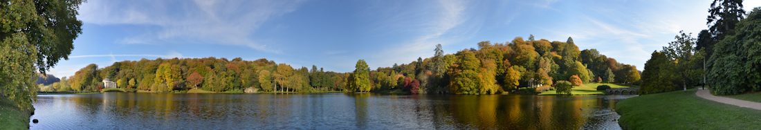
If a picture is worth a thousand words then a panorama must be worth ten thousand, especially a 360° panorama where you can look all around, but how are they created?
My first venture in creating panoramas was in the early 1970s when I applied techniques learned in making mosaics from aerial photographs to a set of images taken from a single location. These included using the “slotted template” technique to let the photographs settle to fit common (control) points and tearing the prints along the join lines to feather the paper. The results were acceptable but did require a lot of effort.
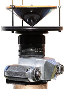 Then in the mid 1970s I had an idea whilst trying to develop a photographic solution for measuring rooms, whilst mapping Annesley Hall in Nottinghamshire, England, and was granted a United Kingdom Patent (#1493188) for an “Optic for instantly photographing an horizon of 360°”. I was then working as a Land Surveyor mapping for a road from the Viphya to Chintechie on the shore of Lake Malawi and then in the deserts of the Arabian Peninsula for a number of years, which is not a good environment for developing and manufacturing an invention and as I was on a Land Surveyor’s wage so funding was also a severe handicap. Although I presented diagrams with curved lines (arcs and parabolas) the patent shows the device with straight lines on the advice of the London Patent Office as I was informed that curved lines were naturally inferred. Another drawback was that the personal computer was still in the future so presenting the 360° panoramas would be a challenge. Although I made no financial gain from my invention it is gratifying to see that it is available today marketed by “pano pro” and similar companies.
This method does however have a limitation in resolution as the circular image only occupies just over 50% of the sensor (digital or film) and varies from top to bottom of the captured image. If the circular image is divided into four zones of equal radius difference the central zone (bottom of the image) is only 6.25% of the whole circle, the next two 18.75% and 31.25% and the outer zone (top of the image) 43.75%, which is a huge range.
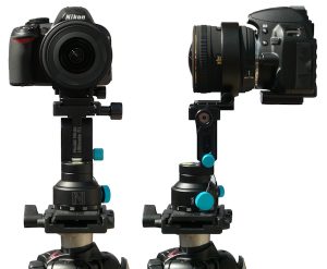
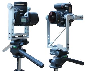 Higher resolution is obtained by taking multiple images and “stitching” them together, which means any movement between exposures has to be dealt with. It is also important that the camera/lens is rotated around the Entrance Pupil (often referred to as the Nodal Point) of the lens. When I first ventured into this field panoramic tripod heads seemed to be prohibitively expensive so I made my own device to rotate the camera/lens horizontally about the Entrance Pupil and to enable zenith shots. The direction of the photographs was controlled by lining up marks on the tripod and head. The device worked well, but having been made to fit a Nikon D70 with a Sigma 8mm lens was no longer suitable when I changed my camera body and later on the lens, so I purchased a Nodal Ninja 3.
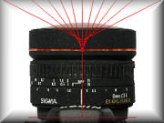
The Nodal Ninja 3 has an advantage in that the directions of the horizontal shots are controlled by “click stops” making aiming faster and more accurate than lining up marks. I use the Nodal Ninja 3 with a Nikon 10.5mm fisheye for most of my 360° panoramas where there is no or little movement in the subject, such as empty rooms or for use with a Leica HDS Scanner.
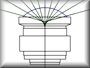
 I shoot eight images around the horizon (45° intervals) plus zenith images if I need to fill the “hole” in the top, but this is often not a requirement. The recommendation usually seems to be six images round the horizon (60° intervals) with this lens, but I chose eight for a number of reasons. The first is probably down to my photogrammetry background but I like a good overlap between images and this arrangement usually results in a “very good” Optimisation in PTGui without the need to add more Control Points. A good overlap provides for good Control Point generation and plenty of area for using the “Mask” tool in PTGui to deal with movement between images. The second is that fisheye lenses do not have a single Entrance Pupil, but its position varies with the angle of the incoming rays and the variation increases as the angle with the principle ray increases. By using the central section of the lens I feel that I am creating a more accurate panorama. This arrangement enables Equirectangular images of 10,000 x 5,000 pixels (50Mp) or larger to be produced.
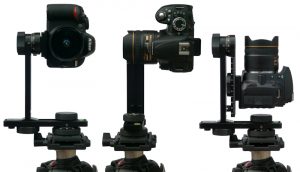
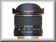
 In an environment with movement, such as people in a room (e.g. a hospitality suite), I find shooting eight images too slow as there is likely to be a significant change in the overlap between the first and last images and the smaller angle of view means that there is less of the subject covered by each overlap restricting the amount of editing possible to correct for movement between the exposures. For this type of environment I started off using a Sigma 4.5mm fisheye with four images around the horizon (90° intervals). The Sigma 4.5mm lens projects a full circle (180°) image on to the APS-C sensor. The Nodal Ninja R1 also has “click stops” making aiming rapid and positive. Once again I am taking more than the normally recommended three images around the horizon (120° intervals) for the same reasons as already mentioned when using the Nikon 10.5mm lens. Having a 90° overlap allows for more scope when selecting parts of the images to compensate for movement in the subject. I take the photographs in a clockwise direction and a person walking from left to right close to the camera can appear twice in the final panorama so being able to remove the person completely from one of the images in an overlap is essential, so reducing the overlap to only 60° with three images around the horizon would be limiting. This arrangement enables Equirectangular images of around 5,000 x 2,500 pixels (12.5Mp) to be produced. I now use a Samyang 8mm with an FX (35mm film size) sensor and generate Equirectangular images of 10,000 x 5,000 pixels (50Mp) or larger.
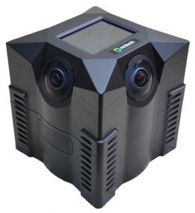 The ideal solution would of course be to have four cameras, each with a full circle fisheye lens, positioned at 90° intervals, so that the whole scene can be photographed in one moment as with the idea of the “Optic for instantly photographing an horizon of 360°”, but to arrange four cameras with their Entrance Pupils (NNPs) coincident is probably physically impossible. However, I learned towards the end of 2010 that two clever people trading as nctech had found a solution to this problem and launched the iSTAR in April 2012.
 The iSTAR records four images to create a panorama with a resolution of 10,000 x 5,000 pixels (50Mp) using the Immersive Studio application created by nctech.
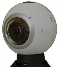
2017 and nctech have raised the resolution to 90Mp with their isis360 Pro camera. Also, affordable dedicated multi-lens cameras have become readily available and although most of these offer lower resolution they have opened up the world of 360° Panoramic Photography to all.
![]()
 |
360° Panoramas Links to 360° (Spherical) Panoramas. The Rock Hewn Churches of Lalibela in Ethiopia, English Churches, Corporate Hospitality Suits, Property, Stereo Anaglyphs, Thermal Imaging and others. |
||
 |
Links to Panorama Related Sites and Software Links include PanoramaStudio, PTGui, Pano2VR, Red Door VR, panoramic tripod head suppliers and 360° panoramas. |
||
 |
Finding the Nodal Point of a Lens For a lens to be used effectively for Photographic Intersection the location of the Front Nodal Point must be accurately determined. |
||
 |
The No Parallax Point Some notes on the No Parallax Point and using it for 360° (Spherical) panoramas. |
||
 |
The Nodal Point The case for the Nodal Point and usage of the term. |
||
![]()